Getting Started - Build Procedure
10:53 AM
In this post I want to talk about the order of a build. When I started I just put everything on one piece at a time and that made it hard to get things looking neat. Sometimes components fell out of the holes while soldering and made things down right ugly. It also took a really long time.
With all that said, I'm going to layout some steps for soldering up your board(s) so that you can get through it quicker and get on to playing.
Prep
It's never fun to sit down to start soldering and realize you don't have something you need half-way through. Get these items together before you start and have them close by for when you need them:- Soldering Iron (I keep mine in the back corner of my desk at all times)
- Solder
- Solder Sucker or wick
- Tip cleaner or damp sponge for cleaning your iron
- Wire Cutters
- Wire Strippers
- Needle nose pliers
- Containment device (blue-tack, rubber bands, piece of cardboard. Anything that keeps your components held flat against the board when you flip it over to start soldering)
- Trash can (for tossing away bits, cutoffs, solder blobs and other things that take up desk space while you're working)
- Third Hands (helpful for populating the board)
Setting Up Your Soldering Iron
Now that you have your tools you have to make sure they're ready. Heat up your soldering iron. I have a variable temp one that I set at around 350°C for soldering and I crank it up a bit more for desoldering. Once it gets hot, melt a bit of solder over the tip in order to tin it. Then wipe off any excess by dabbing it in your tip cleaner. Now, you have your soldering iron ready to go and we can begin.On-board Components
Time to solder components in. I have an order I follow which makes things go smoother and quicker and it goes thusly.- Jumpers - These go first. Since they're so thin I use the stash of resistor, capacitor and diode cutoffs that I have to get them in before anything else. By doing this first I can keep them tight to the board.

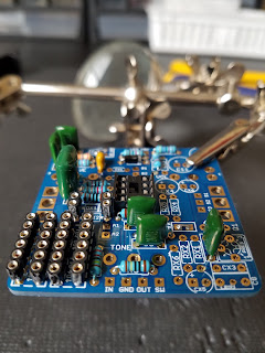
- Resistors - These are the next in size (generally) so I go ahead and populate the board with all the resistors (held in a set of third hands). Then I can stick something like a piece of cardboard over the top, flip over the board and solder everything together in one go.

If you're using blue tack to hold everything in place then you should be good to go. If you're using a piece of cardboard then you can also use a couple of rubber bands around the edges to hold everything in place under tension. I tend to push down in the spot where I'm soldering on accident and let the resistors start falling out in other places. In this case I weighed the board down with a couple of spare tools (as seen above). The end result looks like this:
- Diodes - This is a little trickier. At this point I solder in the diodes that I won't be socketing (like power protection). They're about the same size as resistors so it's pretty straightforward and uses the same technique. You'll notice the diode in the top center of the previous photo. I did that at the same time in this case since it was the same size as the resistors.
- Sockets - I do any DIP (Dual In Line) sockets first. These are the ones you'll be using for ICs in most cases. Then I work on any SIP (Single In Line) sockets which are usually diodes, transistors, or filter resistors/capacitors.

For putting on SIP sockets, break off however many you need and stick them onto the bigger piece in the spacing you need. This will let you use the big section you took them from to position the sockets in the board without them falling out.
- Ceramic and MCC Capacitors - These are the small yellow and orange capacitors. They're pretty tiney so putting them in first makes things easy. (MCC stands for Monolithic Ceramic Capacitor...so yes I was a bit redundant)

- Film Capacitors - The box and greenies go next. I generally work from lowest value to highest since they increase in size as you go (especially with the greenies).
- Electrolytic Capacitors - These are super nice because you can put all the caps in, flip the board, and then the caps hold the board up while you solder (if you do them one height at a time)

Note: In the last picture there's an MCC in the bottom right corner that magically appeared. Well that's what happens when you don't read the build doc thoroughly enough and you realize you're gonna be putting a tiny cap in after all your electrolytics. If that kind of thing does happen to you, then just push the component in and bend the legs outward from the holes so that it holds the component in place and keeps it close to the board.


Off-board Wiring (Pots and Switches)
This is where things get a bit tricky for me. I like to use PCBs with board mounted pots. That way I can use a drill template and I don't have to deal with offboard wires. That procedure typically goes like this:- Drill Enclosure - I drill the enclosure with a template (usually provided in a build guide like the Aion Electronics documents do).
- Mount pots and switches - Put all the pots in the enclosure and screw them on tight enough that they'll hold. You're gonna want them to be able to move a bit to line up with the PCB so don't tighten them too much.
- Align PCB with hardware - Take your PCB and fit each of the legs of the pots and switches into their corresponding locations.
- Solder - Now you can go in and solder all of your connections. Then solder in your wires for your switches and such and you'll be left with a fully working board that now lines up perfectly with your drilled enclosure.
- Drill Enclosure (optional) - I say it's optional because sometimes I just want to try out a circuit before deciding if I'm gonna box it. If you do want to box it then go ahead and drill an enclosure using a generic drill template. They're all over the internet.
- Measure and Cut Wires - This is the tedious part. I figure out how long my wires need to be based on how they'll have to be run in the enclosure (a little extra wire is always better) to get to the pots and swtiches.
Pro Tip: when you're soldering the wires in place, put the opposite ends in the closest socket to hold it and bend it in place for you while you're soldering. - Solder to the Board - I solder the wires to the board next. Then I'll group them and bend them to whatever shape I need so they're close to the pots.
- Solder to the Pots/Switches - I usually have a third hands hold the pot and the board. Then I can manipulate the wire to whatever configuration I need to make the solder join.
- Test Fit - I then test fit everything to make sure I didn't go short on any wires.
Off-board Wiring (Footswitch, LEDs and Jacks)
Now that the board is all set we can get the rest of the hardware mounted and wired up. If your PCB has a space for your LED then you can line that up and solder it in place. If it's off board then you can follow what I do. Follow whatever your favorite true bypass wiring diagram is. I like this one. I won't be showing you how to wire your footswitch (because there's a few different ways), just the order that I run the wires for all of off-board wiring.NOTE: At this point you should have a board that you're able to test. I would recommend testing it out first with a testing rig before boxing it up to make sure it works. Remember "Rock it before you box it".
- Mount the hardware - I first mount all of the hardware in the enclosure (jacks, footswitch, power jack, LED bezel) to make sure nothing is accidentally grounding out or touching anything else.
- Run your ground wires - Pretty straight forward. I run all of the ground wires and solder them up before I do anything else.
- Run your power wires - This will basically be the 9V wire from your board and the positive terminal of the LED (unless you board has the LED built in
- Run your signal wires - Your input and output jacks are next along with soldering the in/out wires from your board to the footswitch.
http://tagboardeffects.blogspot.com/2012/02/offboard-wiring.html
http://madbeanpedals.com/tutorials/downloads/MBP_FootswitchWiring.pdf
http://madbeanpedals.com/tutorials/downloads/Making_a_Prototyping_Rig.pdf
http://effectslayouts.blogspot.com/p/general-layout-notes.html
1 comments
"Very great post.Thanks for sharing this post.
ReplyDeleteTomson Electronics is your go-to Soldering Iron Bits, offering a wide range of top-quality electronic components at unbeatable prices. Whether you're sourcing connectors, resistors, or capacitors, Tomson Electronics provides reliable products and exceptional service for all your wholesale needs. Explore their selection today!"